General
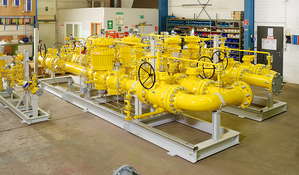
The function of a gas pressure regulating system is to regulate the pressure of the supply line to a constant and lower pressure in the downstream line system. The main reasons for pressure reduction is the limited pressure resistance of built-in parts in the downstream system.
In fuel gas systems for gas turbine power plants in particular, great attention have to be focussed to the gas pressure reduction. The gas turbines are very sensitive during operation in the gas mode. All gas turbines are using a very small range of the operation pressure (range between minimum and maximum operation pressure) and pressure change rate of a gas turbine shall be less than 0.2 bar per second.
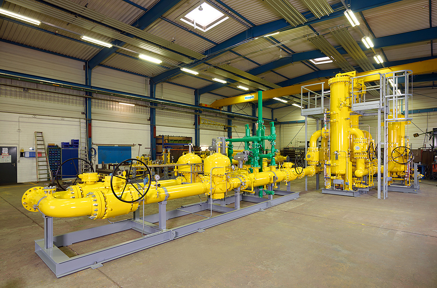
For these reasons, very fast regulators must be used (accuracy class 1) in order to comply with this operating data and to keep the buffer volume as small as possible. During a switchover from the operating line to a standby line due to a malfunction or a maintenance request in the system, an interruption of the gas supply will happen. This gas volume during interruption of the gas supply must be stored in a buffer between the regulating system and the gas turbine to secure that the gas turbine does not stop service or reduce power supply.
If the pressure regulator is not correctly designed across the entire control range or cannot act quickly enough react of pressure changes, then has the selection of the pressure high negative impact on the operation of the system and also on the commercial part and vice versa.
Design codes for pressure regulating systems
The most common design codes for the design of pressure control systems are ASME B31.1 (Power piping code) EN 12186 (Gas supply system – Gas pressure regulating stations for transmission and distribution – Functional requirements). The main difference between the code is the number of pressure regulators required and the pressure protection on the upstream side.
Sizes and pressure rating
Pipe sizes
DN 25 – DN 1000
Pressure rating
ANSI 150 / ANSI 300 / ANSI 600 ANSI 900
Main design criteria
Slam Shut Valve size calculation
Full flow safety blow off valve
Pressure regulator size calculation
Type of pressure regulator
Active/Monitor regulator
With silencer / without silencer
Insulating flange set (outlet)
All design criteria, sizes or pressure ratings can be offered on request